

Exploring New Hardware and Coding
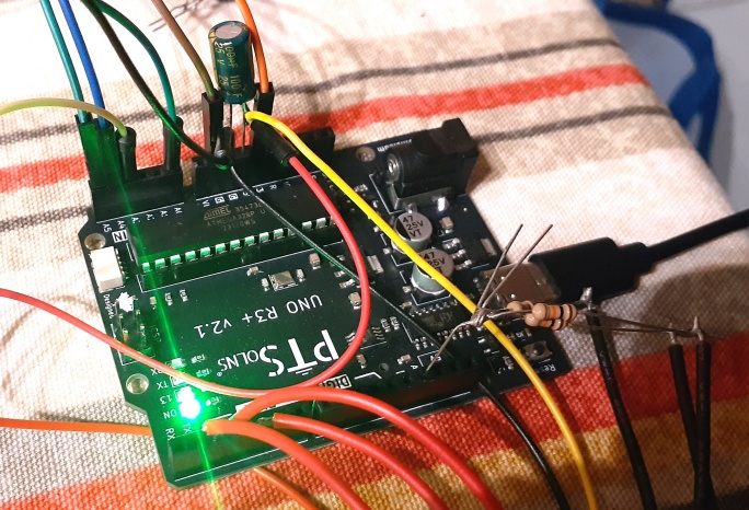
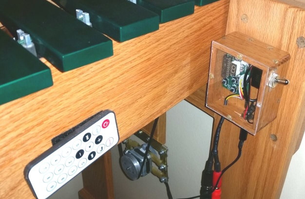
The last stretch of 2025 was consumed by a single overriding task: figuring out the new electronics. Not as a complete system yet — that would come later — but piece by piece. Each new component needed to be understood, wired up, coaxed into working with appropriate code, and proven reliable before it could be trusted in the final build. It was methodical, occasionally frustrating, and enormously satisfying.
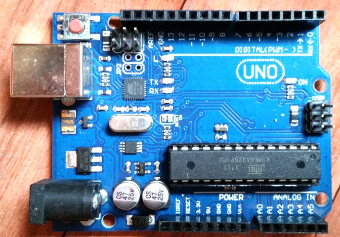
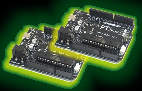
The groundwork for the two-Arduino architecture had been laid in the previous phase — the serial connection between the two units had been confirmed as workable, and that assumption could be carried forward. Now it was time to focus on the individual components at each end of that connection and get them working properly in isolation before bringing everything together.
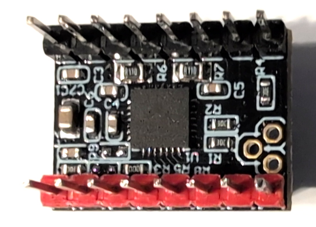
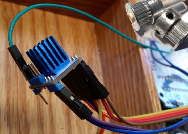
On the motor side, two key upgrades were on the table. The first was a new stepper motor driver — the TMC2209. The drivers used in V1.0 had done the job, but the TMC2209 represented a meaningful step forward: smoother current delivery, quieter operation, and better compatibility with the kind of precise speed control the new FX programs would demand. The second was a new motor itself — a NEMA 17 stepper, a standard form factor widely used in 3D printers and CNC machines, and consequently very easy to source at low cost from almost anywhere in the world.
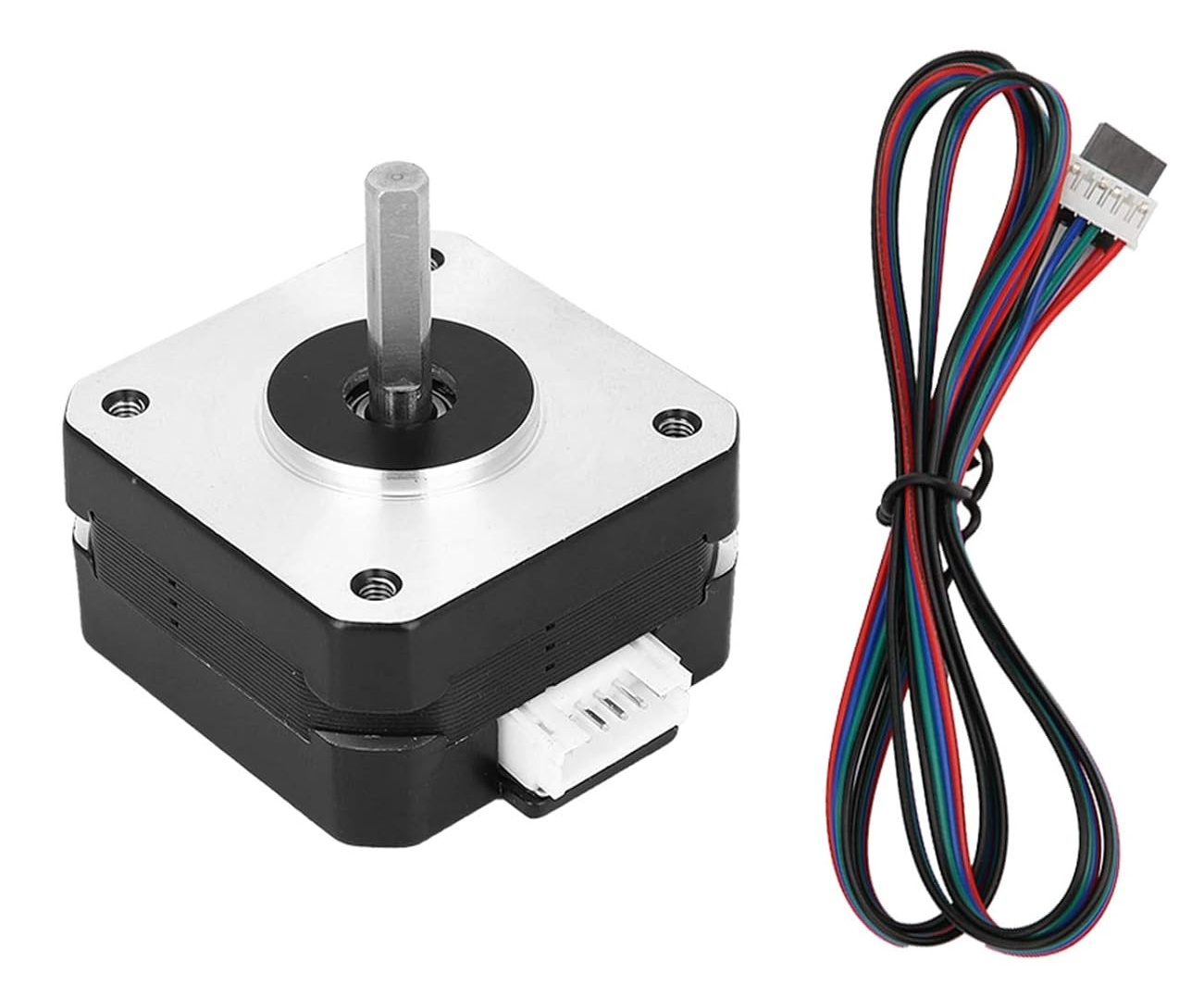
Getting these two working together with the motor Arduino and the existing code — then rewriting that code to function on a dedicated motor-only unit rather than the original single-Arduino setup — was the first substantial coding task of the V2.0 build. The structure of the program had to be rethought from the ground up, separating the motor driving logic cleanly from everything that had previously shared the same loop.
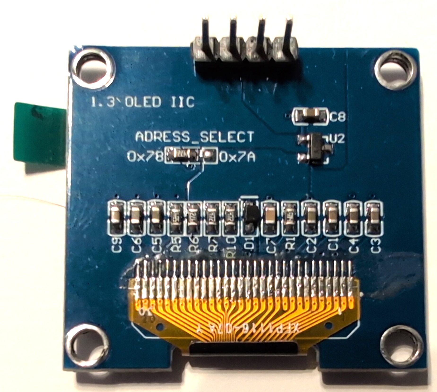
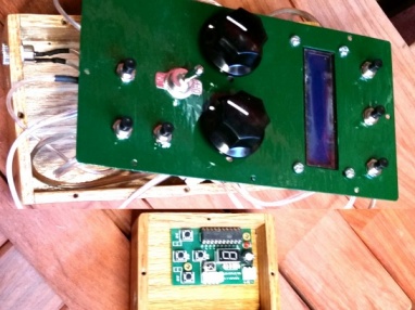
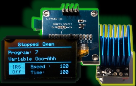
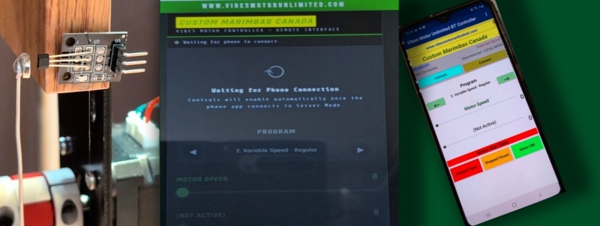
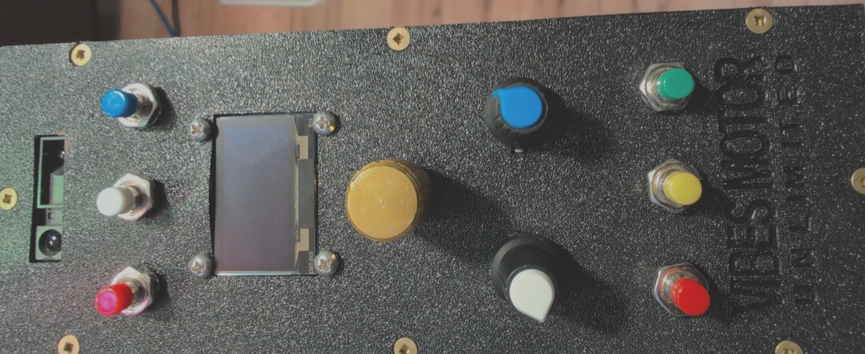
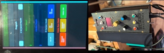
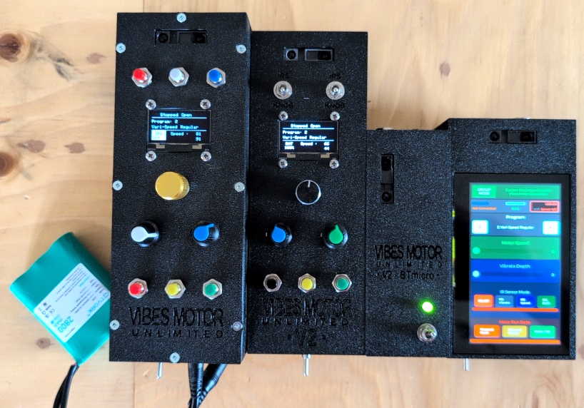
On the interface side, the most visible upgrade was the display. The LCD used in V1.0 had always been a weak point — limited in what it could show and difficult to read at an angle. Its replacement was a 1.3" OLED module, communicating over I²C — the same two-wire protocol used for the inter-Arduino connection. Crisp, high-contrast, and capable of showing far more information in a much more readable format. Getting the OLED library working and driving useful display layouts was its own project, but a rewarding one.
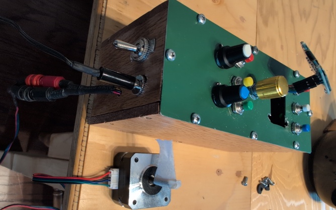
The physical controls also needed rethinking. The two potentiometers used as the main parameter controls — speed and one other variable — were kept. They worked well and felt natural to use. The push buttons for motor run state were also retained; these could be coded in a way that didn't require debouncing, so they added no overhead to the loop. But the old button-based program selection had to go entirely.

Those debounce circuits caused delay in the loop that I didn't want. And using a potentiometer for program selection was too limiting — the range of programs I was planning meant it would never be precise enough.
The solution was a rotary encoder. Unlike a potentiometer, an encoder has no start or end position — it simply registers clockwise or anticlockwise rotation, one step at a time. This meant two things. First, an effectively unlimited number of programs could be navigated with the same comfortable amount of knob movement, regardless of how many were added later. Second — and this was the elegant part — the encoder could be placed on an interrupt on the Arduino. Rather than being polled every loop cycle, it would simply register a change the moment it happened, without touching the main program flow at all.
For something that a performer might reach for only occasionally — changing a program between pieces, or mid-performance at most — this was ideal. The loop runs undisturbed. The motor stays smooth. The encoder fires when it fires. Everything in its right place.